
 After the scrub of space shuttle Atlantis December 2007 launch window, everyone is interested in the ECO sensors. That shuttle component is responsible for the scrub. Unfortunately, detailed information about it is hard to find.
However, I was able to obtain some good information. Most helpful was NASA’s “STS-114 Engine Cut-off Sensor Anomaly Technical Consultation Report“. I also used other NASA sources for my writeup, including information conveyed at the post-scrub press conferences.
Let’s start with some interesting fact that space shuttle program manager Wayne Hale provided in a press conference. According to him, the ECO sensors are an Apollo heritage. Their design dates back to the 1960s. Consequently, they are analog “computer systems”, which look quite strange compared to today’s technology.
I could not find any indication of sensor malfunction prior to STS-114, the “return to flight” mission. However, I have been told that pre-STS-114 flights did not have the same rigor checks in the flight procedure as they exist today. So it may very well be that there always were problems with the sensors, but these were “just” never detected.
It should also be noted that there was never a space shuttle main engine cutoff due to an ECO sensor (I need to correct this a bit later – but let’s keep it this way for the time being). It is believed, however, that on some flights the cutoff happened just a second or so before the ECO sensors would have triggered one. The amount of fuel left in the tank can not be analyzed post-flight, as the external tank is the only non-reusable component of the shuttle stack and lost after being separated from the orbiter.
But now let’s dig down into some hard technical facts: A good starting point are the graphics that NASA posted on the space shuttle home page. I’ll reproduce them here, but due to the blog theme, they are a bit small. Click on each image for a high-res version. It will open up in a new window, so that you can read along.
There is a drawing that puts together all the pieces. It is an excellent starting point:
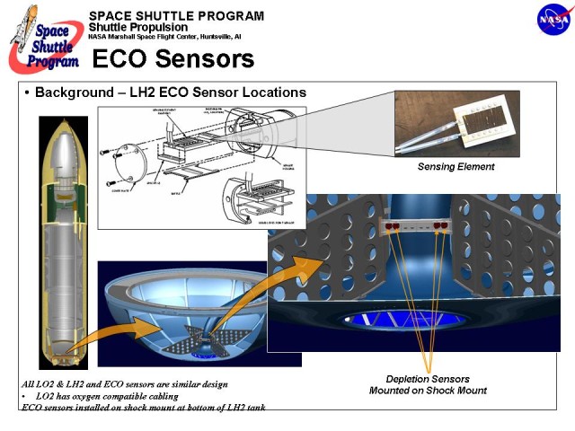 A brief word of caution, though: the picture titles “LH2 ECO Sensor Locations” for a good reason. It is about the liquid hydrogen (LH2) tank sensors. There are also others, as we will see below. Let’s for the time being stick with the LH2 one. As far as I know, the LH2 sensors were also the only trouble source in recent shuttle launch attempts.
This is also where I need to correct myself. There actually have been main engine cutoffs due to ECO sensors, but none of them happened due to the liquid hydrogen sensors. As far as I know, there were three missions where it happened and among them were STS-51F and STS-93.
The image shows that the ECO sensors are located right at the bottom of the tank – which makes an awful lot of sense, as they should indicate depletion. There are four of them mounted in a single row on the shock mount. Each of them has their housing containing the actual sensing element. Even though this is not show on the above overview, let me add that there is are a lot of additional components that make up the so-called “ECO sensor”. That can be nicely seen in this schematic:
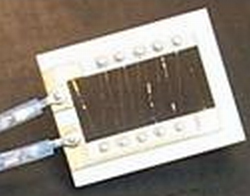 First of all, you’ll probably notice that it is more appropriate to speak of a “sensor system” than just of a “sensor”. If we talk about sensors, most of us simply think about the actual sensing element, seen to the right here. Obviously, that takes us far too short. You must think about the whole system to understand the problem. So think sensor element, electronics and electrical connections. All of this makes up what we call the “ECO Sensor”. In my personal opinion, there is a lot of misleading information and discussions on the public Internet these days. Part of this misunderstanding IMHO seems to stem back to the “sensor” vs. “sensor system” issue. Many folks express that they don’t understand why “such a simple sensor issue” can not be fixed. I guess that was even the motivation to write this post, but, hey, I am becoming off.-topic. On with the technical facts.
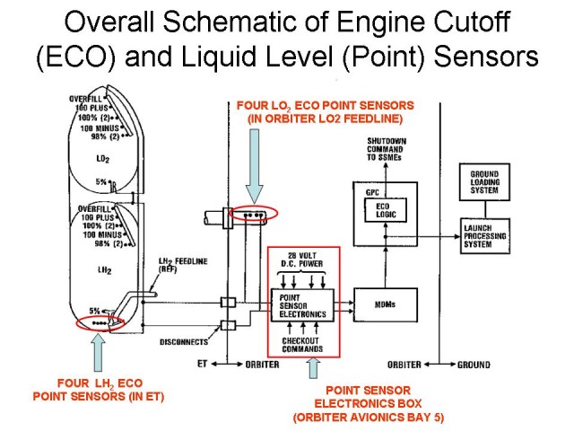
Next, you’ll notice that the ECO sensors are just few of the many sensors that make up the tank level information (the “point sensors”). All of these sensors are the same. The ECOs are in no way special, except for their name. ECO stems from “Engine Cut Off” and is attributed to the fact that these sensors are a emergency line of defense to shut down the engines if other things have already gone wrong (if all goes right, the ECOs are never used, but it is the ECOs that ultimately determine the fact that something went wrong…).
If you count, you’ll find twelve sensors: the four ECO sensors, one 5%, two 98%, one 100% minus, two 100%, one 100% plus and one overfill point sensor. Note that there are sensors both in the liquid hydrogen (LH2) and liquid oxygen (LOX) tank. Each of them has twelve, so there is a total of 24.
A notable difference is the location of the ECO sensors: for LH2, they are at the bottom of the external thank, while for LOX they are in the feedline inside the orbiter. In plain words that means that the LOX ECO sensors report very late while the LH2 sensors report early in the process of tank draining. This can be attributed to the fact that a fuel(LH2)-rich engine shutdown is required. I also assume that the risk of fuel pump overspeed and explosion is by far higher for the LH2 part of the system (but that just my guess, found no hard fact backing it).
The number of sensors at each position tell you something about their importance: it for sure is no accident that most positions are covered by one sensor, the 98% and 100% locations have two and the depletion location has four! Obviously, depletion is a major concern.
Which brings us to the point: why four? Let’s spell it out if it is not clear yet: it’s “just” for redundancy and backup. If there would be just one sensor, a single-sensor failure could be fatal. If it failed dry, it would cause an unnecessary (and comparatively risky) launch abort, if it failed wet and something else goes wrong, it could lead to vehicle destruction. Either way is not really desired, though obviously one case is better than the other.
To mitigate that risk, there are four sensors. But how put these to use? A simplistic approach could be that a poll is taken and the majority wins. So if we have one sensor telling dry and three telling wet, we would go to wet. Obviously, there would be a problem with a 2 dry/2 wet state. So our simplistic model is too simplistic. But I hope it conveyed the idea. What the system really does is a bit different:
First of all, there is a construct called “arming mass”. Keep in mind that the ECO sensors themselves are “just” a backup system to handle the case when other things have gone wrong before. Space shuttle computers continuously monitor engine performance and calculate fuel used. So there is a rough idea of how much fuel is left in the tank at any given moment. However, these calculations may not be 100% perfect and may not detect some malfunction, thus it is risky to rely on them alone. To mitigate that risk, the ECO sensor system has been put in place.
Now let’s take an extreme example. Let’s say an ECO sensor switches to dry just one second after launch. Would you trust it and assume the tank is already drained? I hope not. There are some points in flight where both logic and physics tell us the the tank can not be depleted. In fact, during most of the ascent it can not. But when we come close to main engine cutoff, then fuel may actually be used up. Only at that stage it is useful to look at the ECO sensors. This is what “arming mass” is all about. The shuttle’s computers continuously compute estimated fuel left and only when the estimate comes within the last 8 to 12 seconds of fuel depletion, the ECO sensors are armed.
This has some bonus, too. If an ECO sensor indicates “dry” before we reach arming mass, we can assume the sensor has failed. So that sensor will no longer be able to cast its vote when it later comes to aborting the launch. Please note, however, that it is not possible to detect a “failed wet” sensor in the same way. Sensors are expected to be “wet” during ascent and doing so obviously does not disqualify a sensor.
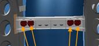 Once the arming mass has reached, shuttle computers look at those sensors with a healthy status. If a single sensor indicates “dry”, computers initially assume a sensor failure. Remember: all sensors are mounted at the same location (see picture to the right), so they theoretically should indicated “dry” all at the same instant. However, that sensor is not disqualified. When now any second of the healthy sensor joins the other one in reading “dry”, shuttle computers assume an actual tank depletion.
They do not wait for the remaining qualified sensors, in a case now assuming these have failed “wet”. So whenever two qualified ECO sensors indicate “dry” after the space shuttle has reached “arming mass”, an abort will most probably be initiated. That means the space shuttle main engines will be cut off in a controlled and non-destructive way (which means a fuel-rich shutdown). Depending on when and how exactly this happens, it may lead to either an abort to the transatlantic landing (TAL) sites or an abort to orbit (ATO). I guess it may even be possible to reach the desired orbit with the help of the orbital maneuvering system if the engine cutoff happens very soon before its originally scheduled time.
Please let me add that the actual procedure for tank depletion must be even more complicated than briefly outlined here. For example, what happens if three of the ECO sensors disqualify themselves by indicating “dry” early in the ascent? Will the remaining single sensor than decide about launch abort? Also, what happens if all four fail early? I don’t like to speculate here, if somebody has the answer, please provide it ;) In any case, you hopefully have gotten some understanding now that the ECO sensor system and putting it to use is not as simple as these days it is often written on the web…
Now let’s look a little bit about where the sensors are located. If you paid attention to the above drawing, you have noticed the black lines which separate parts in the tank from parts in the orbiter (and yet from those at mission control center on the ground).
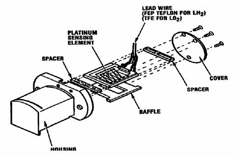
The best picture of the actual ECO sensor housing I could find is this one:
Please note that it shows the ECO sensors during a test, in a test configuration. The mount is different from the actual one in the external tank.
The computers driving the sensors are located in the orbiter’s avionics bay:
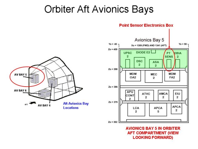
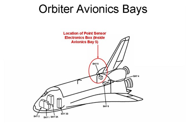 This, and the following, drawings mention the “point sensor box”, PSB for short. Remember that the sensors together are the “point sensors” and the ECO sensors are just point sensors with a special name and function. NASA also lets us know where exactly the point sensor box is located in the shuttle’s aft:
 And finally, we have some more information on the point sensor box itself:
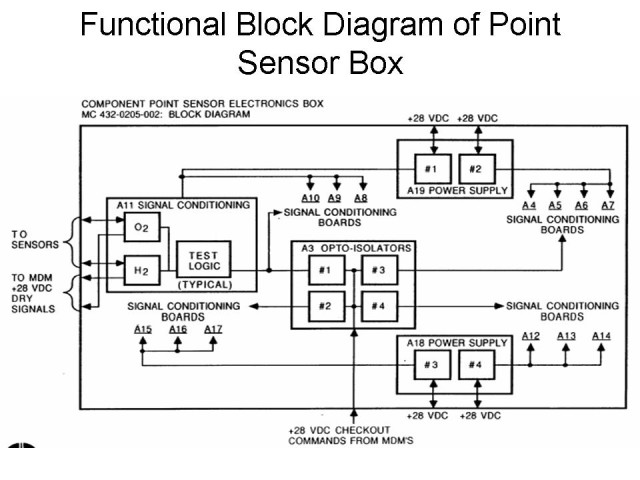 The point sensor box interprets sensor readings. The sensor elements provide a voltage. Certain low voltage level means “dry” while certain high voltage levels are interpreted as “wet”. However, somewhat above the “wet” levels, they indicated “dry” again. This level is reached when there is an open circuit.
NASA also provided an the exploded view of the point sensor box:
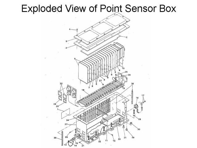
To me, it just looks like a box for electronics and I do not get any further insight from looking at the drawing. But anyways – it’s nice to know…
I could not find pictures of the not-yet-mentioned sensor system parts: the connectors and cables. Somehow the in-tank sensors and the on-board point sensor box must be connected to each other. This is done via some cables and connectors. Those must also be looked at when thinking about the system as whole. Especially as the failure reading we see points to an open circuit. I have read that some of the cable are below external tank foam. So its not easy to get to them.
I have heard that cryogenic temperatures are probably part of the trouble. Because failure readings seem to happen only when the tank ins filled (and thus very cold). One could assume that shrinking of ultra-cold material is part of the problem, but again, I have not found any credible references for this – or any other thermal results.
So it is now probably time to going right to the source. Below, find reproduced the deep technical description from the STS-114 paper quoted right at the start of this posting (quoted text in italics):
The MPS ECO system consists of point-sensors installed in the ET liquid hydrogen (LH2) tank and the Orbiter’s liquid oxygen (LO2) feedline. Point sensor electronics are designed to condition signals and to provide appropriate stimulation of the sensors and associated wiring and connectors.
The point sensor electronics interprets a low resistance at a sensor as the presence of cryogenic liquid, which provides a “wet” indication to the Multiplexer/De-Multiplexer (MDM) for use by on-board General Purpose Computers (GPCs) and the ground Launch Processing System (LPS). Conversely, a high resistance is interpreted as a “dry” indication. The point sensor electronics include circuitry suitable for pre-flight verification of circuit function and are designed to fail “wet”. For example, an open circuit in the sensor, or an open or short in the signal path, will provide a “wet” indication to the MDM. The system is then activated and checked out during launch countdown and remains active during ascent.
An ECO sensor is depicted in the next Figure. The sensor consists of a platinum wire sensing element mounted on an alumina Printed Wiring Board (PWB) and is encased in an aluminum housing. The sensing element acts as a variable resistance which changes on exposure to cryogenic liquid. This resistance variation is detected by post-sensor (signal conditioning) electronics and is used to generate either a “wet” or “dry” indication as noted above.
The ECO system is designed to protect the Space Shuttle Main Engines (SSMEs) from catastrophic failure due to propellant depletion. Flight software is coded to check for the presence of “wet” indications from the sensors within 8 to 12 seconds of SSME shutdown. The software rejects the first “dry” indication observed from any of the ECO sensors, but the presence of at least two more “dry” indications will result in a command to shutdown the SSMEs (i.e., “dry” indications from two of four “good” sensors are required for SSME shutdown). Early SSME shutdown would probably lead to a contingency Trans-Atlantic (TAL) abort. A failed “wet” indication cannot be detected. The system is designed so that LO2 depletion should occur first. However, a failure “wet” indication of three of the four LH2 sensors, coupled with an SSME problem that results in early LH2 depletion, could result in catastrophic failure of a SSME. Failure probability is considered remote, but would almost certainly be catastrophic to the flight vehicle. The system architecture addresses redundancy with one point sensor box containing four groups of sensor conditioner circuit cards. Each card can accommodate one hydrogen and one oxygen sensor. Each card group has its own power converter and one sensor conditioner card from each group services a pair of ECO sensors (again, one hydrogen and one oxygen). Wiring for each of the eight ECO sensors is split into one of two groups of sensors which are routed through separate Orbiter / ET monoball connections.
Let’s wrap-up: I hope you got a more in-depth view of the ECO sensor system by reading this post. At least, I think I have so by doing the research and writing it. Remember that I am no expert in this area, so I may be wrong. If you spot something that needs to be corrected, just drop me a note, for example in the form of a comment.
In regard to recent (STS-122…) developments, the question now is: what should be done if the root cause of the ECO sensor system failure can not be found. I don’t know, I miss too many facts. and my understanding is limited. But my guess is that if there can be rationale found to fly without it, that’s probably the best option to carry out. But hopefully tanking tests will show where it is flawed and a solution can be applied. Either way, I trust those wizards at NASA (and its contractors, of course). They have the have the training, they have the insight and they have the excellence. What else could one ask for?